Table of Contents
Small placement errors matter because thermal energy depends directly on the difference between supply and return temperature. Symmetry and good thermal contact are essential. For heat meter temperature sensor placement, begin with “Identify Supply and Return Beyond Doubt” and then “Keep the Matched Pair Together.” Together, “Identify Supply and Return Beyond Doubt” and “Keep the Matched Pair Together” define the heat meter temperature sensor placement evidence needed before “Choose Representative Pipe Locations.”
After “Choose Representative Pipe Locations,” the heat meter temperature sensor placement workflow continues to “Achieve Correct Immersion Depth” and ends at “Inspect Response, Not Just One Reading.” The move from “Choose Representative Pipe Locations” to “Inspect Response, Not Just One Reading” explains the heat meter temperature sensor placement logic behind this H1.
Identify Supply and Return Beyond Doubt
Trace flow direction and equipment connections instead of relying on old labels. Mark the two insertion points before opening the system. Use drawings and measurements to complete “Identify Supply and Return Beyond Doubt” in heat meter temperature sensor placement. A written “Identify Supply and Return Beyond Doubt” decision keeps installation and operations aligned.
- Verify trace flow direction and equipment connections instead of relying on old labels.
- Document mark the two insertion points before opening the system.
Keep the Matched Pair Together
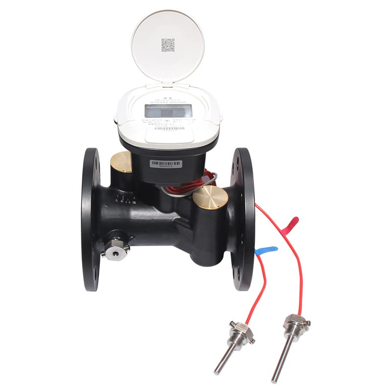
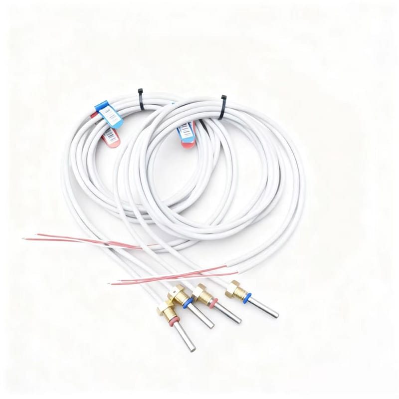
Use sensors supplied and characterized as a pair. Record pair identification and prevent one sensor from being exchanged during installation. A plausible “Keep the Matched Pair Together” result can hide a heat meter temperature sensor placement error. Store “Keep the Matched Pair Together” limits, test conditions and exception ownership.
- Verify use sensors supplied and characterized as a pair.
- Document record pair identification and prevent one sensor from being exchanged during installation.
Choose Representative Pipe Locations
Avoid dead legs, mixing points, bypass junctions and locations exposed to local heat sources. Each sensor should see the water entering or leaving the measured circuit. Share “Choose Representative Pipe Locations” evidence with the heat meter temperature sensor placement stakeholders. If “Choose Representative Pipe Locations” misses its basis, revise the “Choose Representative Pipe Locations” selection and record why.
- Verify bypass junctions and locations exposed to local heat sources.
- Document each sensor should see the water entering or leaving the measured circuit.
Achieve Correct Immersion Depth
Position the sensing element in representative flow according to pocket and pipe guidance. Shallow insertion can make the reading respond to pipe-wall temperature. Give “Achieve Correct Immersion Depth” a dedicated heat meter temperature sensor placement acceptance test. Preserve “Achieve Correct Immersion Depth” values and diagnostics for a repeatable “Achieve Correct Immersion Depth” check.
- Verify position the sensing element in representative flow according to pocket and pipe guidance.
- Document shallow insertion can make the reading respond to pipe-wall temperature.
Make Both Installations Thermally Similar
Use compatible pockets, insertion depths, thermal compound where specified and equivalent insulation. Unequal mounting creates a false temperature difference. Treat “Make Both Installations Thermally Similar” as a complete heat meter temperature sensor placement decision. Recheck “Make Both Installations Thermally Similar” against heat meter temperature sensor placement pipework, controls, interfaces and service access.
- Verify use compatible pockets.
- Document insertion depths.
- Compare thermal compound where specified and equivalent insulation.
- Confirm unequal mounting creates a false temperature difference.
Control Cable Routing and Extensions
Protect cables from heat, moisture and mechanical damage. Follow approved extension methods because conductor resistance can bias some sensor types. Change one “Control Cable Routing and Extensions” variable at a time during heat meter temperature sensor placement diagnosis. The “Control Cable Routing and Extensions” baseline separates “Control Cable Routing and Extensions” hardware, process and installation causes.
- Verify protect cables from heat.
- Document moisture and mechanical damage.
- Compare follow approved extension methods because conductor resistance can bias some sensor types.
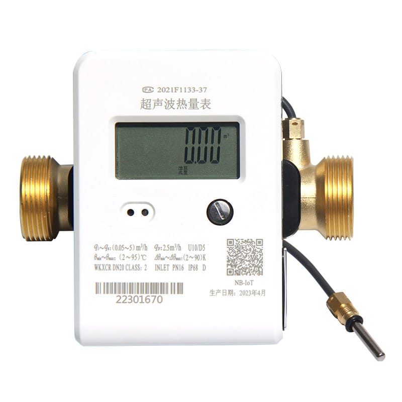
Test Polarity Through Operating Conditions
At heating load, supply should normally exceed return; cooling reverses the expected relationship. Investigate the circuit when the sign conflicts with operation. Close “Test Polarity Through Operating Conditions” with a named heat meter temperature sensor placement owner. For “Test Polarity Through Operating Conditions,” keep its photographs, configuration export and “Test Polarity Through Operating Conditions” comparison readings.
- Verify supply should normally exceed return; cooling reverses the expected relationship.
- Document investigate the circuit when the sign conflicts with operation.
Inspect Response, Not Just One Reading
Trend both temperatures during startup and shutdown. Different time constants can reveal poor contact, unequal pockets or an incorrectly located sensor. For “Inspect Response, Not Just One Reading,” the heat meter temperature sensor placement team ties assumptions to field evidence. Its “Inspect Response, Not Just One Reading” record names the source, unit and “Inspect Response, Not Just One Reading” exception owner.
- Verify trend both temperatures during startup and shutdown.
- Document different time constants can reveal poor contact.
- Compare unequal pockets or an incorrectly located sensor.
Identify Supply and Return Beyond Doubt Decision Table
| Decision | Evidence | Release condition |
|---|---|---|
| Identify Supply and Return Beyond Doubt | Trace flow direction and equipment connections instead of relying on old labels | Release “Identify Supply and Return Beyond Doubt” only after its heat meter temperature sensor placement evidence is accepted |
| Keep the Matched Pair Together | Use sensors supplied and characterized as a pair | Release “Keep the Matched Pair Together” only after its heat meter temperature sensor placement evidence is accepted |
| Choose Representative Pipe Locations | Avoid dead legs, mixing points, bypass junctions and locations exposed to local heat sources | Release “Choose Representative Pipe Locations” only after its heat meter temperature sensor placement evidence is accepted |
| Achieve Correct Immersion Depth | Position the sensing element in representative flow according to pocket and pipe guidance | Release “Achieve Correct Immersion Depth” only after its heat meter temperature sensor placement evidence is accepted |
| Make Both Installations Thermally Similar | Use compatible pockets, insertion depths, thermal compound where specified and equivalent insulation | Release “Make Both Installations Thermally Similar” only after its heat meter temperature sensor placement evidence is accepted |
Five Questions About “Inspect Response, Not Just One Reading”
Which “Identify Supply and Return Beyond Doubt” check comes first for heat meter temperature sensor placement?
Trace flow direction and equipment connections instead of relying on old labels. Mark the two insertion points before opening the system.
Why does keep the matched pair together affect heat meter temperature sensor placement?
Use sensors supplied and characterized as a pair. Record pair identification and prevent one sensor from being exchanged during installation.
How should test polarity through operating conditions be verified?
At heating load, supply should normally exceed return; cooling reverses the expected relationship. Investigate the circuit when the sign conflicts with operation.
When must the heat meter temperature sensor placement basis be reviewed?
Review heat meter temperature sensor placement when inputs to “Identify Supply and Return Beyond Doubt,” “Achieve Correct Immersion Depth” or “Test Polarity Through Operating Conditions” change.
Which details support “Keep the Matched Pair Together” in heat meter temperature sensor placement?
For heat meter temperature sensor placement, provide the inputs for “Identify Supply and Return Beyond Doubt,” the constraints from “Keep the Matched Pair Together” and the evidence expected under “Test Polarity Through Operating Conditions.”
Before approving “Identify Supply and Return Beyond Doubt,” revisit its project assumptions. Trace flow direction and equipment connections instead of relying on old labels. Mark the two insertion points before opening the system. Record the resulting “Identify Supply and Return Beyond Doubt” decision and any site-specific “Identify Supply and Return Beyond Doubt” exception.
Technical references for “Identify Supply and Return Beyond Doubt” include ISO 50001 for “Identify Supply and Return Beyond Doubt”, OIML R 75 for “Keep the Matched Pair Together”, EU Measuring Instruments Directive for “Choose Representative Pipe Locations”, CEN-CENELEC for “Achieve Correct Immersion Depth”. The project specification should name the applicable edition and local rules.
Dingjia options supporting “Keep the Matched Pair Together” include the heat-meter base pipe for “Identify Supply and Return Beyond Doubt”, household heat meter for “Keep the Matched Pair Together”, pipeline heat meter for “Choose Representative Pipe Locations”, matched temperature sensors for “Achieve Correct Immersion Depth”. For “Keep the Matched Pair Together,” send operating conditions and interface requirements to the engineering team before selection. The inquiry should also assign responsibility for “Make Both Installations Thermally Similar” and “Control Cable Routing and Extensions.”