Table of Contents
Calibration is a controlled comparison, not a menu adjustment. The result is only useful when the reference, flow conditions, meter setup and uncertainty are traceable. For ultrasonic water meter calibration, begin with “Define the Calibration Question” and then “Select a Traceable Reference Method.” Together, “Define the Calibration Question” and “Select a Traceable Reference Method” define the ultrasonic water meter calibration evidence needed before “Replicate the Intended Hydraulic Setup.”
After “Replicate the Intended Hydraulic Setup,” the ultrasonic water meter calibration workflow continues to “Choose Flow Points Across the Operating Range” and ends at “Report Uncertainty and Decision Rules.” The move from “Replicate the Intended Hydraulic Setup” to “Report Uncertainty and Decision Rules” explains the ultrasonic water meter calibration logic behind this H1.
Define the Calibration Question
Decide whether the work supports type evaluation, production verification, periodic confirmation or investigation of a suspected bias. The purpose determines the required flow points and acceptance rule. Share “Define the Calibration Question” evidence with the ultrasonic water meter calibration stakeholders. If “Define the Calibration Question” misses its basis, revise the “Define the Calibration Question” selection and record why.
- Verify decide whether the work supports type evaluation.
- Document production verification.
- Compare periodic confirmation or investigation of a suspected bias.
- Confirm the purpose determines the required flow points and acceptance rule.
Select a Traceable Reference Method
Use a gravimetric, volumetric or reference-meter system with documented traceability and an uncertainty suitable for the decision. Record the reference identification and its valid calibration status. Give “Select a Traceable Reference Method” a dedicated ultrasonic water meter calibration acceptance test. Preserve “Select a Traceable Reference Method” values and diagnostics for a repeatable “Select a Traceable Reference Method” check.
- Verify use a gravimetric.
- Document volumetric or reference-meter system with documented traceability and an uncertainty suitable for the decision.
- Compare record the reference identification and its valid calibration status.
Replicate the Intended Hydraulic Setup
Match pipe diameter, connection geometry, orientation and fluid conditions as closely as the procedure requires. Remove air and provide stable pressure so the comparison tests the meter rather than the bench. Treat “Replicate the Intended Hydraulic Setup” as a complete ultrasonic water meter calibration decision. Recheck “Replicate the Intended Hydraulic Setup” against ultrasonic water meter calibration pipework, controls, interfaces and service access.
- Verify match pipe diameter.
- Document connection geometry.
- Compare orientation and fluid conditions as closely as the procedure requires.
- Confirm remove air and provide stable pressure so the comparison tests the meter rather than the bench.
Choose Flow Points Across the Operating Range
Include low flow, representative continuous flow and upper-range conditions. A single mid-range point cannot reveal low-flow threshold behavior or a range-dependent error pattern. Change one “Choose Flow Points Across the Operating Range” variable at a time during ultrasonic water meter calibration diagnosis. The “Choose Flow Points Across the Operating Range” baseline separates “Choose Flow Points Across the Operating Range” hardware, process and installation causes.
- Verify include low flow.
- Document representative continuous flow and upper-range conditions.
- Compare a single mid-range point cannot reveal low-flow threshold behavior or a range-dependent error pattern.
Stabilize Before Recording a Run
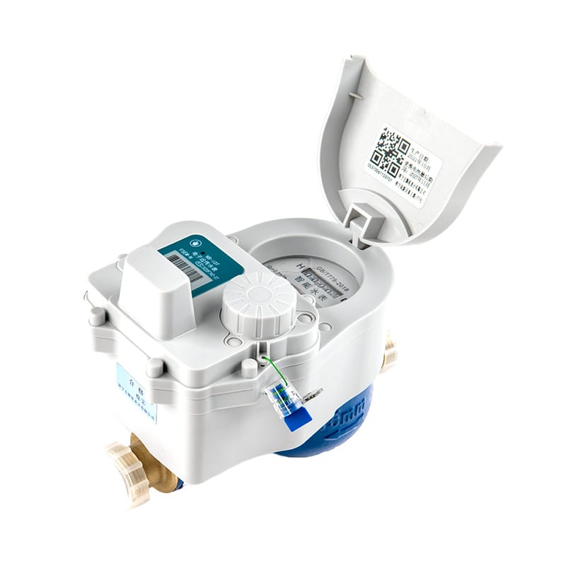
Wait for reference flow, water temperature, pressure and indicated flow to settle. Use a test quantity or duration large enough to reduce timing and resolution effects. Close “Stabilize Before Recording a Run” with a named ultrasonic water meter calibration owner. For “Stabilize Before Recording a Run,” keep its photographs, configuration export and “Stabilize Before Recording a Run” comparison readings.
- Verify wait for reference flow.
- Document water temperature.
- Compare pressure and indicated flow to settle.
- Confirm use a test quantity or duration large enough to reduce timing and resolution effects.
Calculate Error Without Mixing Units
Compare indicated and reference volume on the same basis, preserve the sign convention and record every conversion. Automated calculations still require an independent formula check. For “Calculate Error Without Mixing Units,” the ultrasonic water meter calibration team ties assumptions to field evidence. Its “Calculate Error Without Mixing Units” record names the source, unit and “Calculate Error Without Mixing Units” exception owner.
- Verify compare indicated and reference volume on the same basis.
- Document preserve the sign convention and record every conversion.
- Compare automated calculations still require an independent formula check.
Use Repeatability to Diagnose the Result
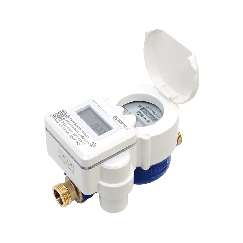
Repeat runs at selected points. Closely grouped results with a consistent offset suggest a systematic influence; scattered results point toward stability, air, signal or test-method problems. Use drawings and measurements to complete “Use Repeatability to Diagnose the Result” in ultrasonic water meter calibration. A written “Use Repeatability to Diagnose the Result” decision keeps installation and operations aligned.
- Verify repeat runs at selected points.
- Document closely grouped results with a consistent offset suggest a systematic influence; scattered results point toward stability.
- Compare signal or test-method problems.
Report Uncertainty and Decision Rules
State the result, expanded uncertainty where applicable, environmental conditions and the rule used to accept or reject. Never present adjustment as calibration evidence without before-and-after data. A plausible “Report Uncertainty and Decision Rules” result can hide a ultrasonic water meter calibration error. Store “Report Uncertainty and Decision Rules” limits, test conditions and exception ownership.
- Verify state the result.
- Document expanded uncertainty where applicable.
- Compare environmental conditions and the rule used to accept or reject.
- Confirm never present adjustment as calibration evidence without before-and-after data.
Define the Calibration Question Decision Table
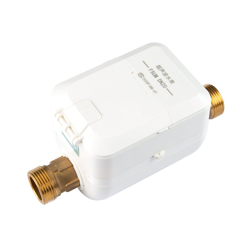
| Decision | Evidence | Release condition |
|---|---|---|
| Define the Calibration Question | Decide whether the work supports type evaluation, production verification, periodic confirmation or investigation of a suspected bias | Release “Define the Calibration Question” only after its ultrasonic water meter calibration evidence is accepted |
| Select a Traceable Reference Method | Use a gravimetric, volumetric or reference-meter system with documented traceability and an uncertainty suitable for the decision | Release “Select a Traceable Reference Method” only after its ultrasonic water meter calibration evidence is accepted |
| Replicate the Intended Hydraulic Setup | Match pipe diameter, connection geometry, orientation and fluid conditions as closely as the procedure requires | Release “Replicate the Intended Hydraulic Setup” only after its ultrasonic water meter calibration evidence is accepted |
| Choose Flow Points Across the Operating Range | Include low flow, representative continuous flow and upper-range conditions | Release “Choose Flow Points Across the Operating Range” only after its ultrasonic water meter calibration evidence is accepted |
| Stabilize Before Recording a Run | Wait for reference flow, water temperature, pressure and indicated flow to settle | Release “Stabilize Before Recording a Run” only after its ultrasonic water meter calibration evidence is accepted |
Five Questions About “Report Uncertainty and Decision Rules”
Which “Define the Calibration Question” check comes first for ultrasonic water meter calibration?
Decide whether the work supports type evaluation, production verification, periodic confirmation or investigation of a suspected bias. The purpose determines the required flow points and acceptance rule.
Why does select a traceable reference method affect ultrasonic water meter calibration?
Use a gravimetric, volumetric or reference-meter system with documented traceability and an uncertainty suitable for the decision. Record the reference identification and its valid calibration status.
How should use repeatability to diagnose the result be verified?
Repeat runs at selected points. Closely grouped results with a consistent offset suggest a systematic influence; scattered results point toward stability, air, signal or test-method problems.
When must the ultrasonic water meter calibration basis be reviewed?
Review ultrasonic water meter calibration when inputs to “Define the Calibration Question,” “Choose Flow Points Across the Operating Range” or “Use Repeatability to Diagnose the Result” change.
Which details support “Select a Traceable Reference Method” in ultrasonic water meter calibration?
For ultrasonic water meter calibration, provide the inputs for “Define the Calibration Question,” the constraints from “Select a Traceable Reference Method” and the evidence expected under “Use Repeatability to Diagnose the Result.”
Technical references for “Define the Calibration Question” include ISO 4064 for “Define the Calibration Question”, NIST Weights and Measures for “Select a Traceable Reference Method”, EPA WaterSense for “Replicate the Intended Hydraulic Setup”, OIML R 49 for “Choose Flow Points Across the Operating Range”. The project specification should name the applicable edition and local rules.
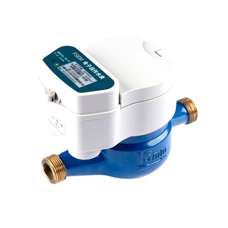
Dingjia options supporting “Select a Traceable Reference Method” include the pipeline network meter for “Define the Calibration Question”, electronic remote meter for “Select a Traceable Reference Method”, contact the metering team for “Replicate the Intended Hydraulic Setup”, ultrasonic water meter for “Choose Flow Points Across the Operating Range”. For “Select a Traceable Reference Method,” send operating conditions and interface requirements to the engineering team before selection. The inquiry should also assign responsibility for “Stabilize Before Recording a Run” and “Calculate Error Without Mixing Units.”