Table of Contents
A heat meter must combine believable flow and a correctly signed temperature difference. Commissioning needs to prove that all three sensing elements and the calculator agree. For heat meter commissioning, begin with “Trace the Supply and Return Circuits” and then “Verify the Matched Sensor Pair.” Together, “Trace the Supply and Return Circuits” and “Verify the Matched Sensor Pair” define the heat meter commissioning evidence needed before “Inspect Flow-Sensor Installation.”
After “Inspect Flow-Sensor Installation,” the heat meter commissioning workflow continues to “Review Calculator Configuration” and ends at “Create a Signed Handover Baseline.” The move from “Inspect Flow-Sensor Installation” to “Create a Signed Handover Baseline” explains the heat meter commissioning logic behind this H1.
Trace the Supply and Return Circuits
Follow the pipework physically and compare it with drawings. Confirm where the flow sensor and each temperature sensor belong before energizing the calculator. Change one “Trace the Supply and Return Circuits” variable at a time during heat meter commissioning diagnosis. The “Trace the Supply and Return Circuits” baseline separates “Trace the Supply and Return Circuits” hardware, process and installation causes.
- Verify follow the pipework physically and compare it with drawings.
- Document confirm where the flow sensor and each temperature sensor belong before energizing the calculator.
Verify the Matched Sensor Pair
Check pair identification, cable integrity and terminal assignment. Do not mix sensors from different pairs or extend one lead differently without approved compensation. Close “Verify the Matched Sensor Pair” with a named heat meter commissioning owner. For “Verify the Matched Sensor Pair,” keep its photographs, configuration export and “Verify the Matched Sensor Pair” comparison readings.
- Verify check pair identification.
- Document cable integrity and terminal assignment.
- Compare do not mix sensors from different pairs or extend one lead differently without approved compensation.
Inspect Flow-Sensor Installation
Confirm full pipe, direction, orientation, straight-run conditions and absence of trapped air. Check that isolation valves are fully open during the acceptance test. For “Inspect Flow-Sensor Installation,” the heat meter commissioning team ties assumptions to field evidence. Its “Inspect Flow-Sensor Installation” record names the source, unit and “Inspect Flow-Sensor Installation” exception owner.
- Verify confirm full pipe.
- Document straight-run conditions and absence of trapped air.
- Compare check that isolation valves are fully open during the acceptance test.
Review Calculator Configuration
Verify fluid, units, sensor type, pulse value or flow interface, integration interval and communication settings against the approved schedule. Use drawings and measurements to complete “Review Calculator Configuration” in heat meter commissioning. A written “Review Calculator Configuration” decision keeps installation and operations aligned.
- Verify pulse value or flow interface.
- Document integration interval and communication settings against the approved schedule.
Challenge Temperature Readings
Compare supply and return values with an independent instrument at stable load. An implausible negative difference often indicates swapped sensors or circuit identification. A plausible “Challenge Temperature Readings” result can hide a heat meter commissioning error. Store “Challenge Temperature Readings” limits, test conditions and exception ownership.
- Verify compare supply and return values with an independent instrument at stable load.
- Document an implausible negative difference often indicates swapped sensors or circuit identification.
Test Energy Response Under Load
Observe flow, temperature difference, instantaneous power and accumulated energy together. The values should change coherently when load changes. Share “Test Energy Response Under Load” evidence with the heat meter commissioning stakeholders. If “Test Energy Response Under Load” misses its basis, revise the “Test Energy Response Under Load” selection and record why.
- Verify temperature difference.
- Document instantaneous power and accumulated energy together.
- Compare the values should change coherently when load changes.

Reconcile Local and Remote Data
Compare display values with M-Bus or BMS points, including units and timestamps. Resolve scaling before any billing or performance analysis begins. Give “Reconcile Local and Remote Data” a dedicated heat meter commissioning acceptance test. Preserve “Reconcile Local and Remote Data” values and diagnostics for a repeatable “Reconcile Local and Remote Data” check.
- Verify compare display values with M-Bus or BMS points.
- Document including units and timestamps.
- Compare resolve scaling before any billing or performance analysis begins.
Create a Signed Handover Baseline
Record totals, temperatures, flow, power, configuration, serial numbers, photographs and communication mapping at acceptance. Treat “Create a Signed Handover Baseline” as a complete heat meter commissioning decision. Recheck “Create a Signed Handover Baseline” against heat meter commissioning pipework, controls, interfaces and service access.
- Verify photographs and communication mapping at acceptance.
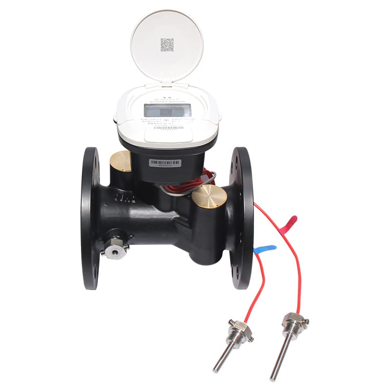
Trace the Supply and Return Circuits Decision Table
| Decision | Evidence | Release condition |
|---|---|---|
| Trace the Supply and Return Circuits | Follow the pipework physically and compare it with drawings | Release “Trace the Supply and Return Circuits” only after its heat meter commissioning evidence is accepted |
| Verify the Matched Sensor Pair | Check pair identification, cable integrity and terminal assignment | Release “Verify the Matched Sensor Pair” only after its heat meter commissioning evidence is accepted |
| Inspect Flow-Sensor Installation | Confirm full pipe, direction, orientation, straight-run conditions and absence of trapped air | Release “Inspect Flow-Sensor Installation” only after its heat meter commissioning evidence is accepted |
| Review Calculator Configuration | Verify fluid, units, sensor type, pulse value or flow interface, integration interval and communication settings against the approved schedule | Release “Review Calculator Configuration” only after its heat meter commissioning evidence is accepted |
| Challenge Temperature Readings | Compare supply and return values with an independent instrument at stable load | Release “Challenge Temperature Readings” only after its heat meter commissioning evidence is accepted |
Five Questions About “Create a Signed Handover Baseline”
Which “Trace the Supply and Return Circuits” check comes first for heat meter commissioning?
Follow the pipework physically and compare it with drawings. Confirm where the flow sensor and each temperature sensor belong before energizing the calculator.
Why does verify the matched sensor pair affect heat meter commissioning?
Check pair identification, cable integrity and terminal assignment. Do not mix sensors from different pairs or extend one lead differently without approved compensation.
How should reconcile local and remote data be verified?
Compare display values with M-Bus or BMS points, including units and timestamps. Resolve scaling before any billing or performance analysis begins.
When must the heat meter commissioning basis be reviewed?
Review heat meter commissioning when inputs to “Trace the Supply and Return Circuits,” “Review Calculator Configuration” or “Reconcile Local and Remote Data” change.
Which details support “Verify the Matched Sensor Pair” in heat meter commissioning?
For heat meter commissioning, provide the inputs for “Trace the Supply and Return Circuits,” the constraints from “Verify the Matched Sensor Pair” and the evidence expected under “Reconcile Local and Remote Data.”
Before approving “Trace the Supply and Return Circuits,” revisit its project assumptions. Follow the pipework physically and compare it with drawings. Confirm where the flow sensor and each temperature sensor belong before energizing the calculator. Record the resulting “Trace the Supply and Return Circuits” decision and any site-specific “Trace the Supply and Return Circuits” exception.
Before approving “Verify the Matched Sensor Pair,” revisit its project assumptions. Check pair identification, cable integrity and terminal assignment. Do not mix sensors from different pairs or extend one lead differently without approved compensation. Record the resulting “Verify the Matched Sensor Pair” decision and any site-specific “Verify the Matched Sensor Pair” exception.
Before approving “Inspect Flow-Sensor Installation,” revisit its project assumptions. Confirm full pipe, direction, orientation, straight-run conditions and absence of trapped air. Check that isolation valves are fully open during the acceptance test. Record the resulting “Inspect Flow-Sensor Installation” decision and any site-specific “Inspect Flow-Sensor Installation” exception.
Technical references for “Trace the Supply and Return Circuits” include CEN-CENELEC for “Trace the Supply and Return Circuits”, ISO 50001 for “Verify the Matched Sensor Pair”, OIML R 75 for “Inspect Flow-Sensor Installation”, EU Measuring Instruments Directive for “Review Calculator Configuration”. The project specification should name the applicable edition and local rules.
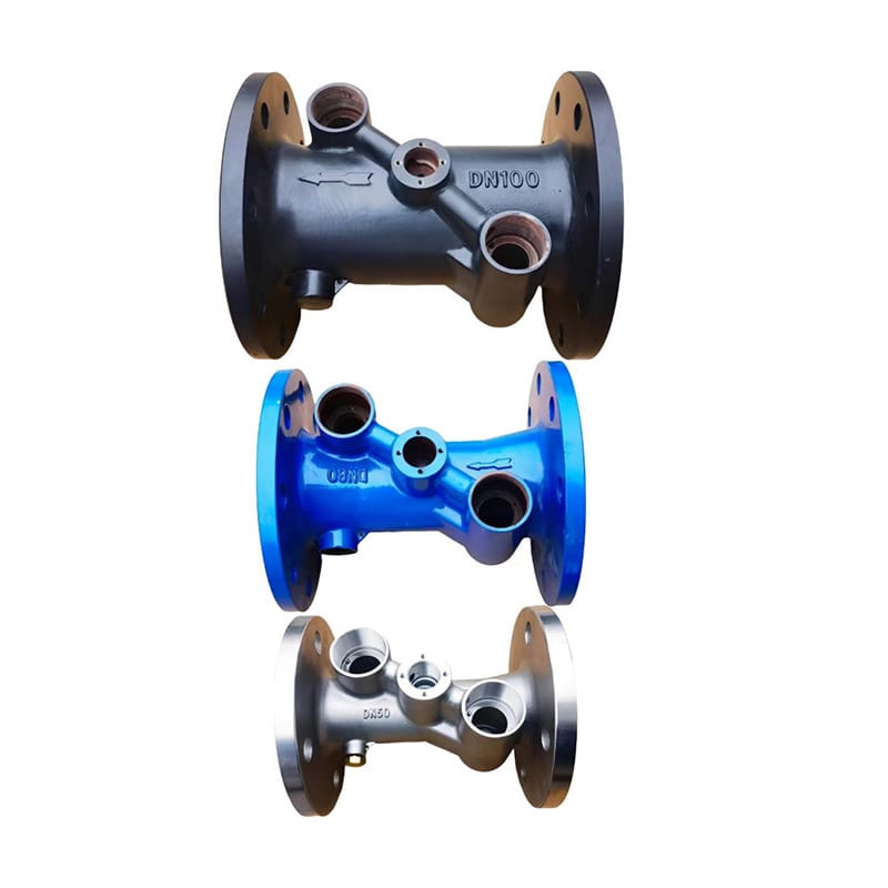
Dingjia options supporting “Verify the Matched Sensor Pair” include the matched temperature sensors for “Trace the Supply and Return Circuits”, heat-meter base pipe for “Verify the Matched Sensor Pair”, household heat meter for “Inspect Flow-Sensor Installation”, pipeline heat meter for “Review Calculator Configuration”. For “Verify the Matched Sensor Pair,” send operating conditions and interface requirements to the engineering team before selection. The inquiry should also assign responsibility for “Challenge Temperature Readings” and “Test Energy Response Under Load.”