Table of Contents
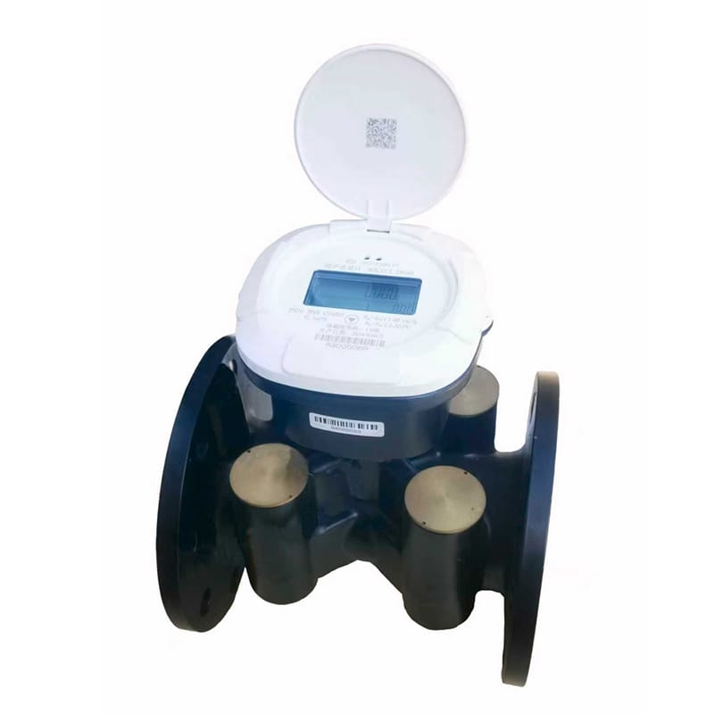
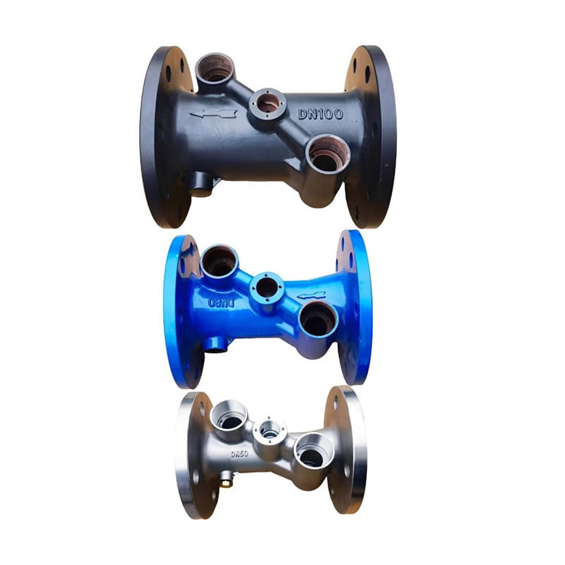
The base pipe fixes the hydraulic diameter, pressure boundary and ultrasonic path. It must be selected with the transducers and calculator as one measurement assembly. For heat meter base pipe selection, begin with “Define Diameter From Flow, Not Convention” and then “Match End Connections and Pressure Class.” Together, “Define Diameter From Flow, Not Convention” and “Match End Connections and Pressure Class” define the heat meter base pipe selection evidence needed before “Choose a Compatible Wetted Material.”
After “Choose a Compatible Wetted Material,” the heat meter base pipe selection workflow continues to “Protect the Acoustic Geometry” and ends at “Specify Incoming Inspection.” The move from “Choose a Compatible Wetted Material” to “Specify Incoming Inspection” explains the heat meter base pipe selection logic behind this H1.
Define Diameter From Flow, Not Convention
Evaluate velocity and meter operating range at minimum and design flow. Existing pipe size is an interface constraint, not automatically the correct measuring section. For “Define Diameter From Flow, Not Convention,” the heat meter base pipe selection team ties assumptions to field evidence. Its “Define Diameter From Flow, Not Convention” record names the source, unit and “Define Diameter From Flow, Not Convention” exception owner.
- Verify evaluate velocity and meter operating range at minimum and design flow.
- Document existing pipe size is an interface constraint.
- Compare not automatically the correct measuring section.
Match End Connections and Pressure Class
Specify thread, flange standard, face-to-face length and rating. Check companion flanges, gaskets and fasteners as part of the pressure boundary. Use drawings and measurements to complete “Match End Connections and Pressure Class” in heat meter base pipe selection. A written “Match End Connections and Pressure Class” decision keeps installation and operations aligned.
- Verify face-to-face length and rating.
- Document check companion flanges.
- Compare gaskets and fasteners as part of the pressure boundary.
Choose a Compatible Wetted Material
Consider fluid chemistry, temperature, corrosion, potable-water obligations and connected pipe materials. Record the complete wetted-material specification. A plausible “Choose a Compatible Wetted Material” result can hide a heat meter base pipe selection error. Store “Choose a Compatible Wetted Material” limits, test conditions and exception ownership.
- Verify consider fluid chemistry.
- Document potable-water obligations and connected pipe materials.
- Compare record the complete wetted-material specification.
Protect the Acoustic Geometry
Transducer seats, reflectors and internal diameter determine the path. Manufacturing tolerances and surface condition must remain consistent. Share “Protect the Acoustic Geometry” evidence with the heat meter base pipe selection stakeholders. If “Protect the Acoustic Geometry” misses its basis, revise the “Protect the Acoustic Geometry” selection and record why.
- Verify transducer seats.
- Document reflectors and internal diameter determine the path.
- Compare manufacturing tolerances and surface condition must remain consistent.
Review Pressure Loss and Flow Profile
Avoid abrupt reducers or internal steps near the measuring path. Calculate system pressure loss at the actual design flow. Give “Review Pressure Loss and Flow Profile” a dedicated heat meter base pipe selection acceptance test. Preserve “Review Pressure Loss and Flow Profile” values and diagnostics for a repeatable “Review Pressure Loss and Flow Profile” check.
- Verify avoid abrupt reducers or internal steps near the measuring path.
- Document calculate system pressure loss at the actual design flow.
Provide Sensor and Calculator Interfaces
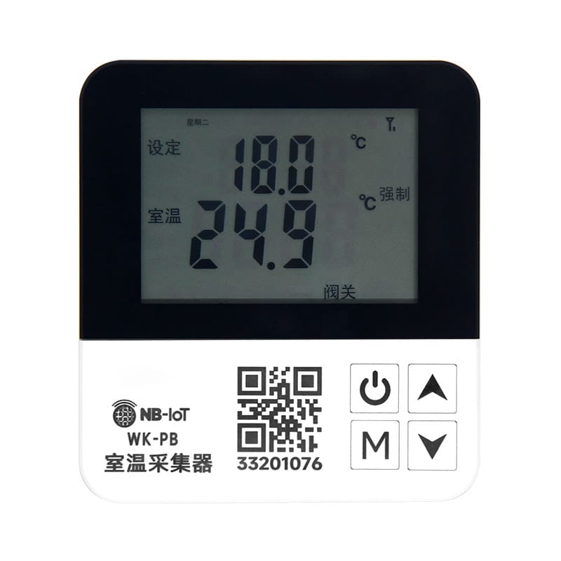
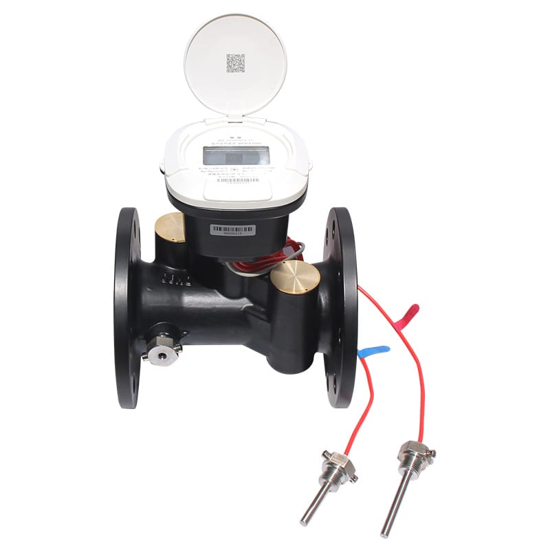
Confirm transducer type, cable connection, temperature-sensor provisions and calculator compatibility before approving the pipe section. Treat “Provide Sensor and Calculator Interfaces” as a complete heat meter base pipe selection decision. Recheck “Provide Sensor and Calculator Interfaces” against heat meter base pipe selection pipework, controls, interfaces and service access.
- Verify confirm transducer type.
- Document cable connection.
- Compare temperature-sensor provisions and calculator compatibility before approving the pipe section.
Plan Installation and Replacement Space
Check face-to-face dimensions, pipe supports, valve isolation and access to sensor ports. Larger sizes need a safe lifting and alignment plan. Change one “Plan Installation and Replacement Space” variable at a time during heat meter base pipe selection diagnosis. The “Plan Installation and Replacement Space” baseline separates “Plan Installation and Replacement Space” hardware, process and installation causes.
- Verify check face-to-face dimensions.
- Document valve isolation and access to sensor ports.
- Compare larger sizes need a safe lifting and alignment plan.
Specify Incoming Inspection
Verify dimensions, markings, connection condition, material documents where required, pressure-test evidence and transducer-seat cleanliness. Close “Specify Incoming Inspection” with a named heat meter base pipe selection owner. For “Specify Incoming Inspection,” keep its photographs, configuration export and “Specify Incoming Inspection” comparison readings.
- Verify verify dimensions.
- Document connection condition.
- Compare material documents where required.
- Confirm pressure-test evidence and transducer-seat cleanliness.

Define Diameter From Flow, Not Convention Decision Table
| Decision | Evidence | Release condition |
|---|---|---|
| Define Diameter From Flow, Not Convention | Evaluate velocity and meter operating range at minimum and design flow | Release “Define Diameter From Flow, Not Convention” only after its heat meter base pipe selection evidence is accepted |
| Match End Connections and Pressure Class | Specify thread, flange standard, face-to-face length and rating | Release “Match End Connections and Pressure Class” only after its heat meter base pipe selection evidence is accepted |
| Choose a Compatible Wetted Material | Consider fluid chemistry, temperature, corrosion, potable-water obligations and connected pipe materials | Release “Choose a Compatible Wetted Material” only after its heat meter base pipe selection evidence is accepted |
| Protect the Acoustic Geometry | Transducer seats, reflectors and internal diameter determine the path | Release “Protect the Acoustic Geometry” only after its heat meter base pipe selection evidence is accepted |
| Review Pressure Loss and Flow Profile | Avoid abrupt reducers or internal steps near the measuring path | Release “Review Pressure Loss and Flow Profile” only after its heat meter base pipe selection evidence is accepted |
Five Questions About “Specify Incoming Inspection”
Which “Define Diameter From Flow, Not Convention” check comes first for heat meter base pipe selection?
Evaluate velocity and meter operating range at minimum and design flow. Existing pipe size is an interface constraint, not automatically the correct measuring section.
Why does match end connections and pressure class affect heat meter base pipe selection?
Specify thread, flange standard, face-to-face length and rating. Check companion flanges, gaskets and fasteners as part of the pressure boundary.
How should plan installation and replacement space be verified?
Check face-to-face dimensions, pipe supports, valve isolation and access to sensor ports. Larger sizes need a safe lifting and alignment plan.
When must the heat meter base pipe selection basis be reviewed?
Review heat meter base pipe selection when inputs to “Define Diameter From Flow, Not Convention,” “Protect the Acoustic Geometry” or “Plan Installation and Replacement Space” change.
Which details support “Match End Connections and Pressure Class” in heat meter base pipe selection?
For heat meter base pipe selection, provide the inputs for “Define Diameter From Flow, Not Convention,” the constraints from “Match End Connections and Pressure Class” and the evidence expected under “Plan Installation and Replacement Space.”
Before approving “Define Diameter From Flow, Not Convention,” revisit its project assumptions. Evaluate velocity and meter operating range at minimum and design flow. Existing pipe size is an interface constraint, not automatically the correct measuring section. Record the resulting “Define Diameter From Flow, Not Convention” decision and any site-specific “Define Diameter From Flow, Not Convention” exception.
Before approving “Match End Connections and Pressure Class,” revisit its project assumptions. Specify thread, flange standard, face-to-face length and rating. Check companion flanges, gaskets and fasteners as part of the pressure boundary. Record the resulting “Match End Connections and Pressure Class” decision and any site-specific “Match End Connections and Pressure Class” exception.
Technical references for “Define Diameter From Flow, Not Convention” include OIML R 75 for “Define Diameter From Flow, Not Convention”, EU Measuring Instruments Directive for “Match End Connections and Pressure Class”, CEN-CENELEC for “Choose a Compatible Wetted Material”, ISO 50001 for “Protect the Acoustic Geometry”. The project specification should name the applicable edition and local rules.
Dingjia options supporting “Match End Connections and Pressure Class” include the household heat meter for “Define Diameter From Flow, Not Convention”, pipeline heat meter for “Match End Connections and Pressure Class”, matched temperature sensors for “Choose a Compatible Wetted Material”, heat-meter base pipe for “Protect the Acoustic Geometry”. For “Match End Connections and Pressure Class,” send operating conditions and interface requirements to the engineering team before selection. The inquiry should also assign responsibility for “Review Pressure Loss and Flow Profile” and “Provide Sensor and Calculator Interfaces.”