Table of Contents
Introduction
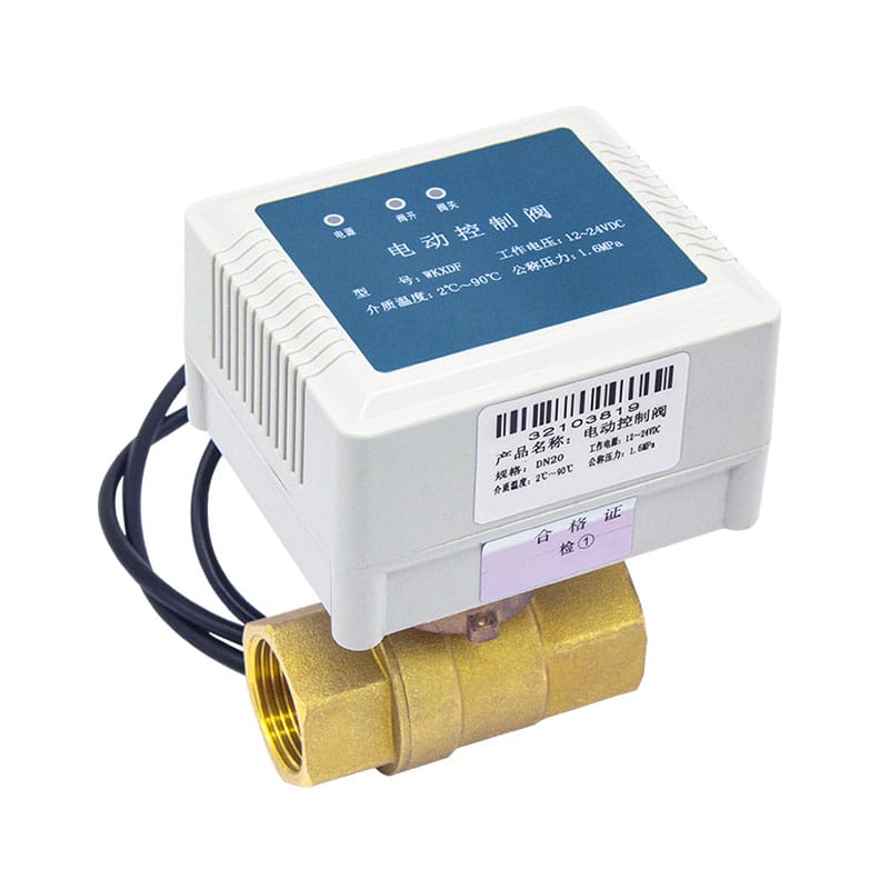
In most modern industrial systems, flow control is no longer handled manually. What used to depend on operators turning handwheels or adjusting mechanical valves has gradually shifted toward automated control systems. Among all automation components, the electric actuated control valve has quietly become one of the most widely used devices in fluid regulation.
You will find it in water treatment plants, HVAC networks, chemical processing lines, and even energy systems where process stability matters more than anything else.
From a manufacturer’s perspective, the real value of this type of valve is not just “opening and closing flow.” It is about maintaining stable system behavior under changing pressure, temperature, and flow conditions—without constant human intervention.
To understand why this device is so widely adopted, we need to look beyond definitions and focus on how it actually behaves inside real industrial systems.
How an Electric Actuated Control Valve Actually Works in Real Systems
At its core, the operating logic is straightforward, but the engineering behind it is what makes the system reliable.
A control system—typically a PLC or DCS—sends an electrical signal. This signal is not just a simple ON or OFF command. In most industrial setups, it is a proportional signal such as 4–20mA or 0–10V. This is where the concept of “modulating control” begins.
The electric actuator receives this signal and starts converting electrical energy into mechanical movement. Inside the actuator, a motor drives a gearbox system that amplifies torque and reduces speed. This controlled movement is then transferred to the valve stem, adjusting the internal valve opening.
What makes this system valuable is the feedback loop. The actuator does not simply move and stop—it continuously checks position status and corrects deviations. This is what allows stable flow regulation even when upstream pressure or downstream demand changes.
In practical terms, it behaves like this:
- System demand changes
- Signal is updated automatically
- Valve adjusts opening proportionally
- Flow stabilizes without manual intervention
This is why electric actuated valves are now closely linked with industrial automation systems and smart control architectures.
Different Valve Structures Used with Electric Actuation
One thing often overlooked is that “electric actuated control valve” is not a single product type. It is a combination of actuator technology and valve body design.
In real engineering applications, three structures dominate:
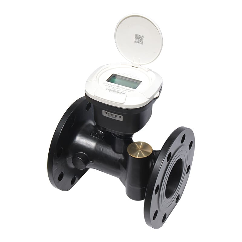
Ball-type configurations are commonly used where fast shut-off and low flow resistance are required. They respond quickly and are structurally simple, making them suitable for general industrial pipelines.
Butterfly-type designs are more common in large-diameter systems. Their compact structure makes them practical in HVAC systems and water distribution networks where space and weight matter.
Globe-type structures are chosen when precision is more important than speed. These are typically used in systems that require continuous modulation rather than simple opening or closing.
Each structure behaves differently under flow conditions, which is why selection is always based on system requirements rather than preference.
Where These Valves Are Actually Used in Industry
In real-world applications, electric actuated control valves are rarely used in isolation. They are part of a larger process system.
In water treatment plants, they regulate flow distribution between filtration, dosing, and discharge systems. Stability in this environment directly affects water quality consistency.
In HVAC systems, they are responsible for balancing chilled or heated water across different zones in buildings. Without proper modulation, temperature control becomes inconsistent.
In chemical processing, the focus shifts to corrosion resistance and precise dosing. Here, valve material selection becomes as important as actuator performance.
In energy and steam systems, temperature and pressure variations are extreme. The valve must respond smoothly without causing system shock or instability.
Even in irrigation and agricultural systems, automation has increased reliance on electrically controlled valves to reduce manual labor and improve water efficiency.
What Matters When Selecting an Electric Actuated Control Valve
Selection is where many system failures begin, not because of poor products, but because of mismatched requirements.
The first factor is always the medium being controlled. Water, steam, gas, and chemical fluids behave differently under pressure and temperature changes, which directly affects sealing and corrosion resistance requirements.
The second factor is control method compatibility. Modern systems are rarely standalone; they need to integrate with PLC or DCS platforms. Signal type and response accuracy matter more than many users initially expect.
The third factor is operating environment. Outdoor installations, humid environments, or hazardous zones require different protection levels, especially for the actuator housing.
Electrical configuration is another critical point. Industrial systems may operate under different voltage standards, and actuator compatibility must align with system infrastructure.
Finally, there is the issue of flow capacity. Undersized or oversized valves can both lead to unstable regulation, even if the actuator itself is functioning correctly.
Electric vs Pneumatic Control Systems in Practical Use
In industrial discussions, electric and pneumatic systems are often compared, but in real engineering practice, the decision is usually driven by infrastructure rather than preference.
Electric systems are easier to integrate into digital automation platforms. They do not require compressed air systems and can be directly connected to control logic units.
Pneumatic systems, on the other hand, are often preferred in environments where rapid emergency response or intrinsic safety is critical.
Over the past years, more facilities have shifted toward electric systems due to increasing demand for centralized monitoring and digital control.
Issues That Commonly Appear During Operation
In long-term operation, most issues are not sudden failures but gradual performance deviations.
One common situation is when the valve stops responding correctly to signals. In most cases, this is related to signal mismatch or wiring instability rather than mechanical damage.
Another issue appears when the valve does not fully reach its intended position. This is often related to torque limitation settings or internal mechanical resistance.
Leakage problems usually point to sealing wear or improper alignment during installation, not actuator malfunction.
In some cases, actuator overheating can occur due to excessive cycling or load conditions that exceed design assumptions.
Most of these issues can be avoided through proper installation and routine inspection rather than reactive maintenance.
Installation Perspective That Often Gets Ignored
From a field application point of view, installation quality often determines service life more than product design.
A properly installed valve should always align naturally with pipeline direction, without introducing mechanical stress on the body.
Electrical connections should be protected from moisture and vibration, especially in outdoor or industrial environments.
Integration with automation systems should be tested before full operation, not after commissioning begins.
In practice, many early system issues are traced back to installation rather than product failure.
Manufacturing and Custom Engineering Perspective
From a manufacturing standpoint, electric actuated control valves are rarely “standard products” in real projects.
Different industries require different configurations, including material selection, actuator torque adjustment, signal compatibility, and sealing structure design.
Some systems require corrosion resistance for chemical exposure. Others require stable performance under high temperature or continuous modulation conditions.
This is where customization becomes essential. A manufacturer’s role is not only production but also ensuring that the valve behaves correctly in a specific system environment.
Conclusion
Electric actuated control valves have become a core part of modern industrial automation because they solve a simple but critical problem: stable and precise flow control without constant manual adjustment.
Their working principle is straightforward in concept but highly engineered in execution, combining electrical control, mechanical movement, and feedback regulation into a single system.
In real industrial environments, success depends not only on the valve itself but also on correct selection, proper installation, and system-level integration.
As automation systems continue to evolve, electric actuated control valves will remain an essential component in ensuring process stability, efficiency, and controllability across industries.
FAQ
What is an electric actuated control valve used for?
An electric actuated control valve is used to automatically regulate fluid flow in pipelines. It is widely applied in water treatment, HVAC systems, chemical processing, and industrial automation systems where precise flow control is required.
How does an electric actuated control valve work?
It works by receiving an electrical control signal (such as 4–20mA or 0–10V), which drives the actuator motor. The motor adjusts the valve opening proportionally, allowing accurate control of flow rate in real time.
What industries commonly use electric actuated control valves?
These valves are commonly used in water treatment plants, HVAC systems, oil and gas pipelines, chemical industries, power plants, and automated industrial production systems.
What is the difference between electric and pneumatic control valves?
Electric actuated control valves use electrical energy for operation and are easier to integrate with automation systems, while pneumatic control valves use compressed air and are often preferred in fast-response or safety-critical environments.
What should be considered when selecting an electric actuated control valve?
Key factors include fluid type, pressure and temperature conditions, control signal compatibility, valve size, actuator torque, and environmental protection requirements such as IP rating or explosion-proof design.