Table of Contents
A reliable billing or energy-management system begins long before the calculator displays its first reading. Heat meter installation must place the flow sensor, matched temperature sensors, calculator, and communication wiring where they can represent the same thermal circuit. A meter can be correctly sized and still produce questionable data when the flow direction is reversed, a probe is fitted in the wrong pipe, air remains in the measuring section, or the commissioning record is incomplete.
This guide gives HVAC contractors, utility engineers, building operators, and system integrators a practical workflow for heat meter installation. It focuses on decisions that can be checked in the field. Always apply the meter-specific manual, approved design drawings, local legal-metrology rules, and site safety procedures before using any general recommendation.
What a Heat Meter Installation Must Measure
A thermal energy meter calculates transferred energy from three inputs: the volume or mass of heat-transfer fluid, the temperature in the supply line, and the temperature in the return line. The EU Measuring Instruments Directive describes a thermal energy meter as a complete instrument or a combined instrument made from a flow sensor, a matched temperature-sensor pair, and a calculator. That definition is useful during heat meter installation because it prevents the components from being treated as unrelated devices.
The meter is measuring energy across a defined boundary. If the flow sensor belongs to one branch while a temperature probe reads another, the calculator receives internally inconsistent inputs. The first task in heat meter installation is therefore to mark the exact supply and return pipes serving the load to be measured.
Define the Heat Meter Installation Boundary
Start with a marked-up hydraulic diagram. Identify the heat source, consumer, bypasses, mixing valves, pumps, hydraulic separators, and every route that could allow fluid to cross the intended boundary. A sound heat meter installation measures all flow delivering energy to the consumer and excludes circulation that does not belong to that consumer.
- Confirm whether the application is heating, cooling, or combined heating and cooling.
- Record the normal, minimum, and maximum operating flow expected at the measuring point.
- Confirm supply and return temperatures, pressure class, pipe size, and available straight length.
- Identify isolation valves and a safe method for draining, flushing, filling, and venting.
- Decide whether the reading is for billing, tenant allocation, plant optimization, or system monitoring.
For a district or commercial network, compare the boundary with the project鈥檚 metering schedule and point list. The related guide to ultrasonic heat meters for district heating explains how meter data fits into remote reading and long-term energy control.
Select the Heat Meter Installation Components
Meter size should follow the expected flow range, not pipe diameter alone. Oversizing can place normal operation near the lower end of the measuring range, while undersizing can add excessive pressure loss or exceed the permitted flow. Before heat meter installation, compare the design flow profile with the selected meter鈥檚 approved operating limits and installation orientation.
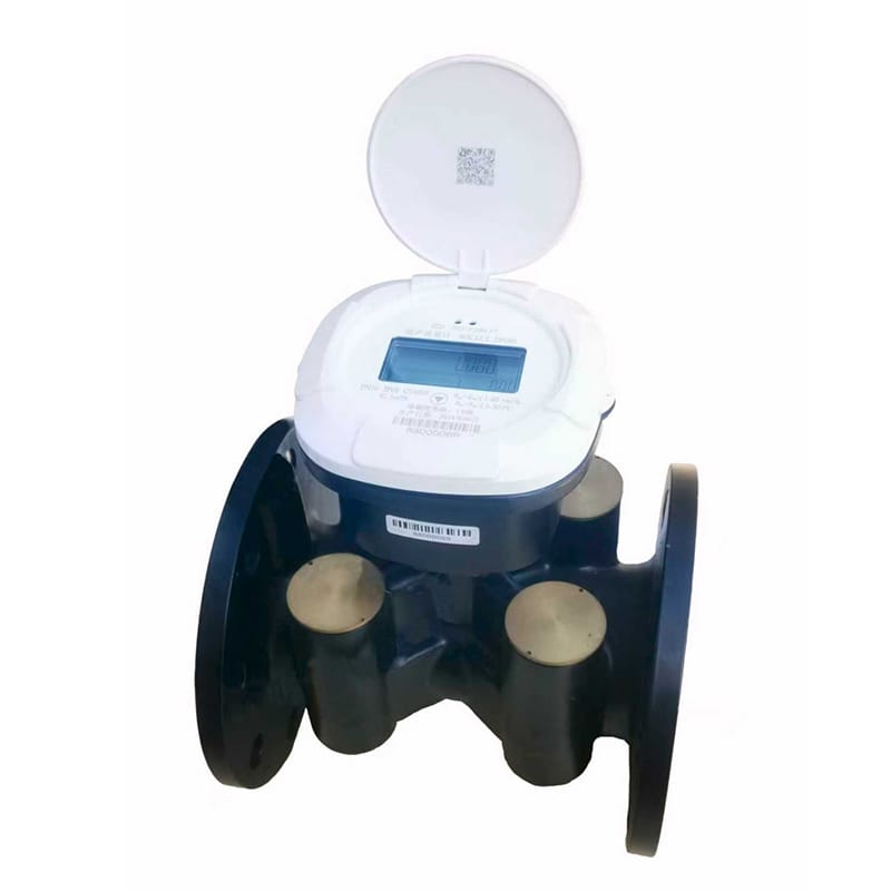
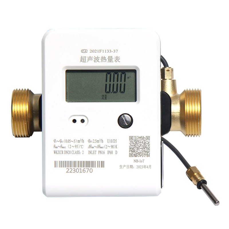
Compact meters are practical for apartments and small commercial circuits, while larger networks may require separate flow sensors, calculator mounting, and longer sensor leads. Review the household ultrasonic heat meter for compact applications and the pipeline network ultrasonic heat meter for larger distribution systems. For a building-level selection workflow, see the guide on choosing a compact heat meter.
Keep the temperature sensors as the supplied matched pair unless the approved documentation explicitly permits replacement or rematching. The OIML R 75-1 recommendation for heat meters provides an authoritative reference for the metrological functions and subassemblies that project teams should understand.
Prepare the Pipework for Heat Meter Installation
Pipe preparation is part of heat meter installation, not a separate plumbing task. Isolate and depressurize the circuit under the site鈥檚 approved procedure. Flush debris before exposing the measuring section, and make sure welding residue, sealing compound, or scale cannot enter the flow sensor. Fit any required strainer in the position specified by the design and meter manual.
Avoid locations where air can collect or where the pipe may not remain full. Keep pumps, control valves, bends, reducers, and other flow disturbances outside the straight lengths stated by the meter manufacturer. General diagrams from Ofgem鈥檚 heat meter installation illustrations show why trapped air, reversed probes, and proximity to fittings can undermine measurement. The product manual still takes priority because required straight lengths vary by sensor design.
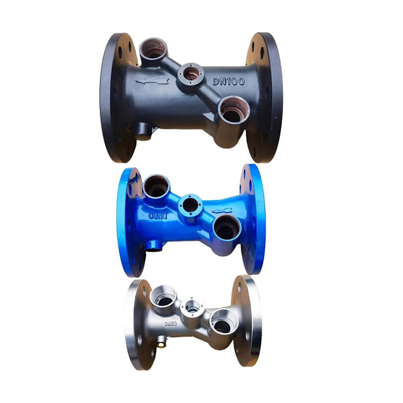
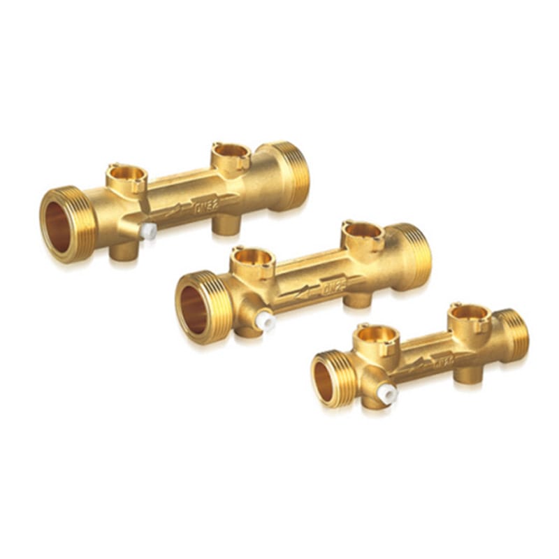
Connection hardware must match the pipe size and pressure class without introducing a step or projecting gasket into the bore. Dingjia supplies heat meter base pipe sections for DN50鈥揇N300 networks and DN15鈥揇N40 circuits; the final selection should follow the meter model and approved drawing.
Install the Flow Sensor Correctly
Check the arrow on the sensor body before tightening the connections. Reversed flow is one of the easiest heat meter installation errors to prevent and one of the most disruptive to correct after filling. Confirm whether the selected model is approved for installation in the supply pipe, return pipe, or either location, then make the calculator configuration agree with that choice.
- Support the adjoining pipe so the meter body does not carry mechanical load.
- Align flanges or threaded connections without forcing the sensor into position.
- Use clean, correctly sized gaskets that do not protrude into the flow path.
- Follow the permitted horizontal, vertical, or angled mounting orientation.
- Leave the display, seals, wiring terminals, and service points accessible.
After mechanical heat meter installation, refill slowly and vent the circuit. A sudden pressure surge can damage components, while residual air can create unstable flow readings. Inspect every joint before insulation conceals it.
Position Sensors During Heat Meter Installation
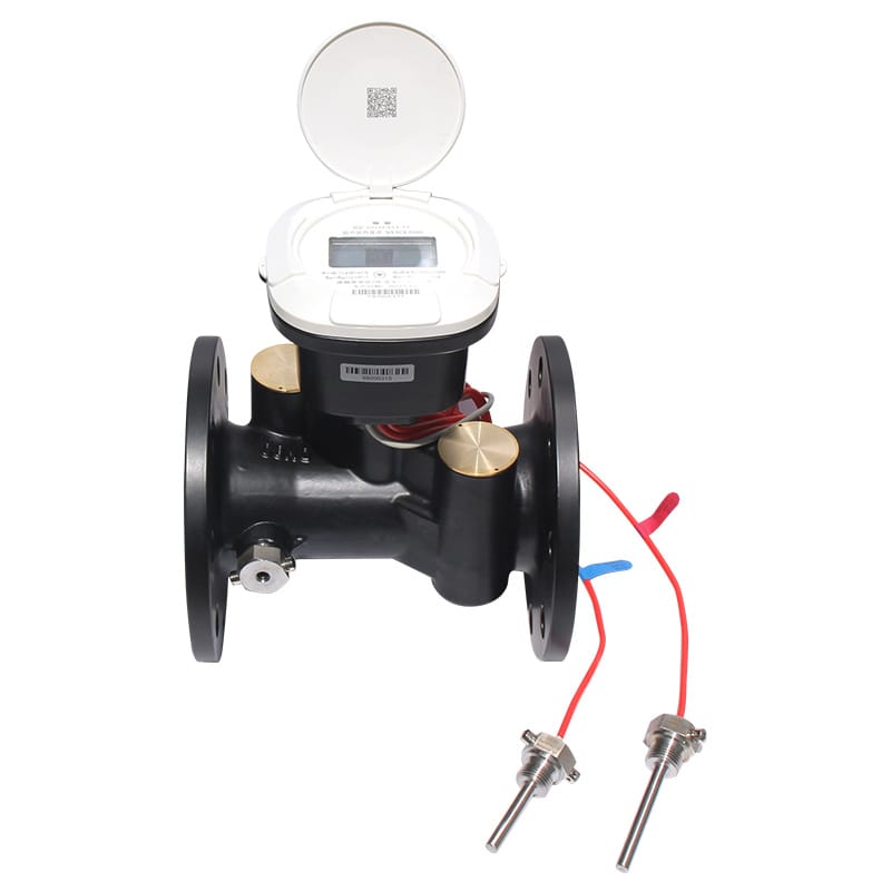
The two temperature readings must represent the same energy-transfer boundary as the flow reading. During heat meter installation, place one probe in the supply line and the other in the corresponding return line. Follow the color coding, labels, wiring diagram, and calculator terminal assignments supplied with the meter rather than relying on site convention alone.
Both probes should have comparable thermal contact and response conditions. Insert them to the specified depth, use approved pockets or direct-immersion fittings, and apply the required sealing method. Avoid placing one sensor in a well-mixed main and the other in a stagnant branch. Explore the available temperature sensor configuration when preparing the bill of materials, but confirm compatibility with the calculator and approval documentation before ordering.
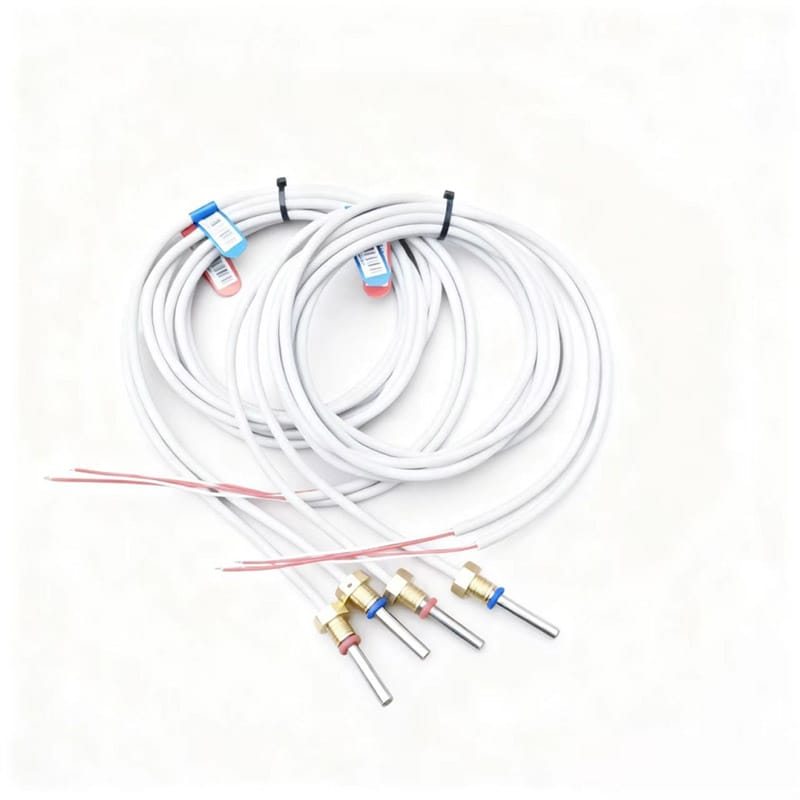
Do not shorten, extend, splice, or interchange sensor leads unless the manufacturer鈥檚 approved instructions allow it. Cable resistance and connection quality can affect the temperature difference seen by the calculator, especially when the actual differential temperature is small.
Complete the Heat Meter Installation Wiring
The calculator needs a dry, accessible location within its permitted ambient conditions. Protect it from condensation, direct heat, vibration, and accidental impact. A maintainable heat meter installation leaves enough cable length for service but avoids loose coils near power conductors or sources of electromagnetic interference.
Terminate the flow input, temperature sensors, power supply, pulse outputs, and communication bus against the approved wiring diagram. Keep polarity and shielding consistent. Label both ends of each cable with the meter identifier used in the controls point list. Where M-Bus, pulse, or another remote-reading interface is required, record the address and communication parameters before closing the enclosure.
Regulatory and contractual requirements vary by market. European projects can use the CEN-CENELEC overview of harmonized thermal-energy-meter standards and the applicable national implementation as starting references. They do not replace local approval, installer qualification, or project specifications.
Commission and Validate the Heat Meter Installation
Commissioning converts a completed heat meter installation into a defensible measuring point. Do not accept a live display as proof that the system is correct. Compare the meter with the hydraulic diagram, wiring schedule, device labels, and building-management-system point list.
- Verify that indicated flow direction agrees with actual circulation.
- Check that supply temperature is assigned to the supply channel and return temperature to the return channel.
- Confirm that flow, temperature difference, instantaneous power, and accumulated energy respond plausibly as the load changes.
- Inspect the event log for reversed flow, sensor faults, air, low battery, or communication errors.
- Confirm remote values and engineering units against the local display.
- Record serial numbers, addresses, initial readings, configuration, seals, and photographs.
If readings appear implausible, stop and diagnose the input signals rather than applying an undocumented correction factor. A heat meter installation should be traceable from physical components to displayed and transmitted values.
Common Heat Meter Installation Mistakes and Symptoms
| Mistake | Likely symptom | Field check |
|---|---|---|
| Flow sensor installed backward | Reverse-flow alarm, zero total, or implausible power | Compare body arrow, pipe flow, and calculator setting |
| Supply and return probes exchanged | Negative or reversed temperature difference | Trace each labeled probe to its pipe and terminal |
| Air trapped at the sensor | Unstable or intermittent flow | Verify pipe remains full and vent the circuit safely |
| Meter oversized for normal load | Long periods near the lower measuring range | Compare logged flow with the selected operating range |
| Disturbance too close to sensor | Reading changes unexpectedly with pump or valve position | Check actual straight lengths against the product manual |
| Communication setup incomplete | Local reading is valid but remote point is missing | Confirm address, baud rate, polarity, mapping, and units |
Use this table during heat meter installation as a diagnostic starting point, not as a substitute for the device manual. Corrective work on a billing meter may also require authorized personnel, resealing, or formal reverification.
Create a Useful Heat Meter Installation Handover Record
A complete heat meter installation record should let another engineer understand the measuring point without reopening every enclosure. Include the approved schematic, meter and sensor serial numbers, model and size, mounting location, supply-or-return configuration, communication address, initial readings, commissioning results, photographs, and the date of installation.
Also define who will inspect alarms, review consumption trends, replace batteries where applicable, and manage periodic verification required by the jurisdiction or contract. Good documentation shortens future troubleshooting and protects the continuity of meter data.
Heat Meter Installation Checklist
- The measurement boundary matches the hydraulic diagram.
- Meter size and operating range match the expected flow profile.
- The flow sensor is installed in the approved pipe, direction, and orientation.
- The pipe is full, flushed, supported, and free from trapped air.
- The matched temperature sensors are in the correct supply and return locations.
- Wiring, shielding, addressing, and engineering units are verified.
- Local and remote values respond plausibly during commissioning.
- Serial numbers, settings, readings, seals, and photographs are recorded.
Use this checklist at design review, before filling, during commissioning, and at handover. Repeating the checks at each stage is easier than correcting a concealed heat meter installation after the system enters service.
Frequently Asked Questions
Where should the flow sensor be installed?
Use the pipe location and orientation approved for the selected model. Some meters are configured for supply installation, others for return installation, and some allow either when the calculator is configured correctly. The product manual and approved design govern the heat meter installation.
Can the two temperature sensors be replaced separately?
Normally, the sensors should be treated as a matched pair. Do not interchange, extend, or replace one probe unless the manufacturer鈥檚 approved procedure and applicable metrology rules permit it.
How much straight pipe is required?
The required inlet and outlet lengths depend on the flow-sensor design and nearby disturbances. Follow the exact meter manual. During heat meter installation, measure the available straight length rather than estimating it from drawings.
Why does a newly installed meter show zero energy?
Check for zero or reversed flow, exchanged temperature sensors, a very small temperature difference, wiring faults, trapped air, and calculator configuration. Diagnose each input independently before replacing the meter.
What should be recorded at commissioning?
Record device and sensor serial numbers, configuration, initial readings, flow direction, temperature channels, communication settings, alarm status, seal details, photographs, and the responsible installer. This evidence makes the heat meter installation easier to audit and maintain.
Plan the Heat Meter Installation Before Work Starts
Send Dingjia your system diagram, pipe size, flow range, and communication requirements for a heat meter installation review before work begins.